
Introduction:
As information changes, this article will be updated. It is always UNDER CONSTRUCTION.
Every now and then an amateur astronomer asks me what equipment they will need to do good CCD imaging, or what the techniques are for good imaging. The questions lead to more questions, more answers, and a lot of typing! Compiled below are the most frequently asked questions I hear when it comes to the topics of CCD astronomy. The hope is that this article will get read, and that the reader is prompted to continue research into this rewarding field of astronomy. Many of the images in this paper have been reduced in size. To see the full size image with details, just click on the image.

These articles set the stage for the rest of this discussion. Be sure that you want to get involved with CCD imaging. It is a time-consuming and patience- testing activity. It does not become easy overnight and can lead to a lot of frustration. Plan on imaging one object per night. Plan on a long night. Plan on spending most of the evening focusing! If you are the type to get frustrated easily, then take a few steps back and do some wide field astrophotography. The results are lovely, and require minimal equipment and effort. If you love checklists, details, and have a way with electronics when it’s cold outside and the bugs are biting, then this might be for you!
What is a CCD?
The term CCD is an acronym for “Charged Couple Device”. What does this mean? Now it is time to talk about a little theory. A CCD chip is a thin piece of silicon in a wafer format. These wafers are sensitive to light in an interesting way. When light falls upon them, the “Photoelectric Effect” takes hold; electrons are knocked free from the crystalline structure of the silicon and deposited into small units or wells. There is one well per pixel. When the image is complete, the electrons are sent into a holding register where they are counted. The more electrons in a given register, the brighter that pixel will be. That is the simplified version. Those looking for a more complete theoretical discussion should see one of the many fine books about CCD theory now available. One good one is: CCD Astronomy : Construction and Use of an Astronomical CCD Camera by Christian Buil, Emmanuel Davoast (Translator), January 1991, Willmann-Bell; ISBN: 0943396298.
What is Quantum Efficiency?
This is a measure of the CCD chip’s sensitivity to the various wavelengths of light in the spectrum. In an ideal world, a CCD would have 100% Quantum Efficiency across the visible wavelengths of light, assuming one wishes to study just those wavelengths. This is an imperfect world, and chips have varying sensitivities across the spectrum as can be seen in the graph below (source: SBIG)

Signals and Noises:
Every CCD imager detects both signal and noise. Signals are easily dealt with, and are desirable. Noise is a random component of an image and is difficult to reduce once it is in an image. The best way to deal with it is to prevent it from happening.
Sources of Signal Information:
- Image: This is what you want to get the most of! This is the signal incoming from the object(s) you are trying to image.
- Thermal: This is the CCD’s dark current, the slow and steady growth of signal caused by the heat inside the CCD itself. This is lowered by cooling the chip (usually thermoelectric cooling) and can be removed by subtracting a dark frame from the final image.
- Bias: This is signal information that is on the CCD chip before an image is even taken. This signal can be removed by subtracting a bias frame (0 second exposure) from the completed image. All images downloaded from a CCD contain bias information.
Sources of Noise Information:
- Thermal Noise: This is heat noise caused by inconsistencies in the rate at which thermal signals are generated in the chip. This can also come from components within the imager such as an amplifier circuit.
- Reception Variation: This is caused by the inconsistent reception of photons from the source. Examples would be clouds, dew, ice, haze, an airplane, etc.
- Read Noise: This is caused by errors in the amplifier circuit.
- Quantization Noise: This is noise created in the analog-to- digital conversion of the data.
- Sensitivity Variations: CCD’s do not have the same sensitivity from pixel to pixel nor across the whole chip.
- Light Leaks! Yes, sometimes unwanted signals come from light leaking into your optical path. This is more common with open tubed telescopes, but also a bright LED or PC screen can get its light into your CCD. It should be noted that LEDs are bright in the IR, and CCDs are very sensitive to IR.
What is a Light Frame?


This is the image one is trying so hard to obtain. The light frame is the data from the actual imaging of the object. This is taken through a lens system or telescope with the shutter open and lens cap off. A light frame also contains noise: thermal, light leaks, radio interference, read noise, etc. All of this has to be removed to get your final image.
What is a Dark Frame?

A dark frame is an image of the same duration and temperature as the light frame taken with the CCD imager with the lens cap on or shutter closed. This image contains a “map” of the dark signal across the surface of the chip. During processing, the dark frame is subtracted from the light frame using software to remove the dark current signal. This is one of the easiest ways to improve your images. If there is one piece of advice to follow: take and subtract dark frames! Your images will show the improvement. To improve your images, and especially if you are doing photometry, you should take many darks and then average them together. An additional suggestion: Take the dark frame integration just before or after your imaging run so that the temperature conditions of the imager are close to the conditions used for the image itself. If you have a CCD which has thermal control, then you can take many dark frames at a variety of temperatures: Make a library! I have taken 10 dark frames for each temperature (C): 10, 5, 0, -5, -10, -20, down to -50C. That is cold. Used in conjunction with bias frames (a 0-second integration), the darks can then be averaged together then scaled to ANY integration time that you have made. Take 10 bias frames as well… at each temperature.
What is a Bias Frame?

A bias frame is an image, taken again with the lens cap on, for a 0 second duration and at the same temperature as the light frame. This is a “map” or record of the bias signal and can be removed by subtracting it from the final light frame image and its dark frame during processing. Note that the bias is also used to scale your darks for different integration times. If you use multiple darks and multiple flats, then the bias frames must be averaged together first then the master bias subtracted from ALL other images first, before any other processing. All frames from a CCD imager contain bias information that needs to be removed by subtraction.
What is a Flat Field?
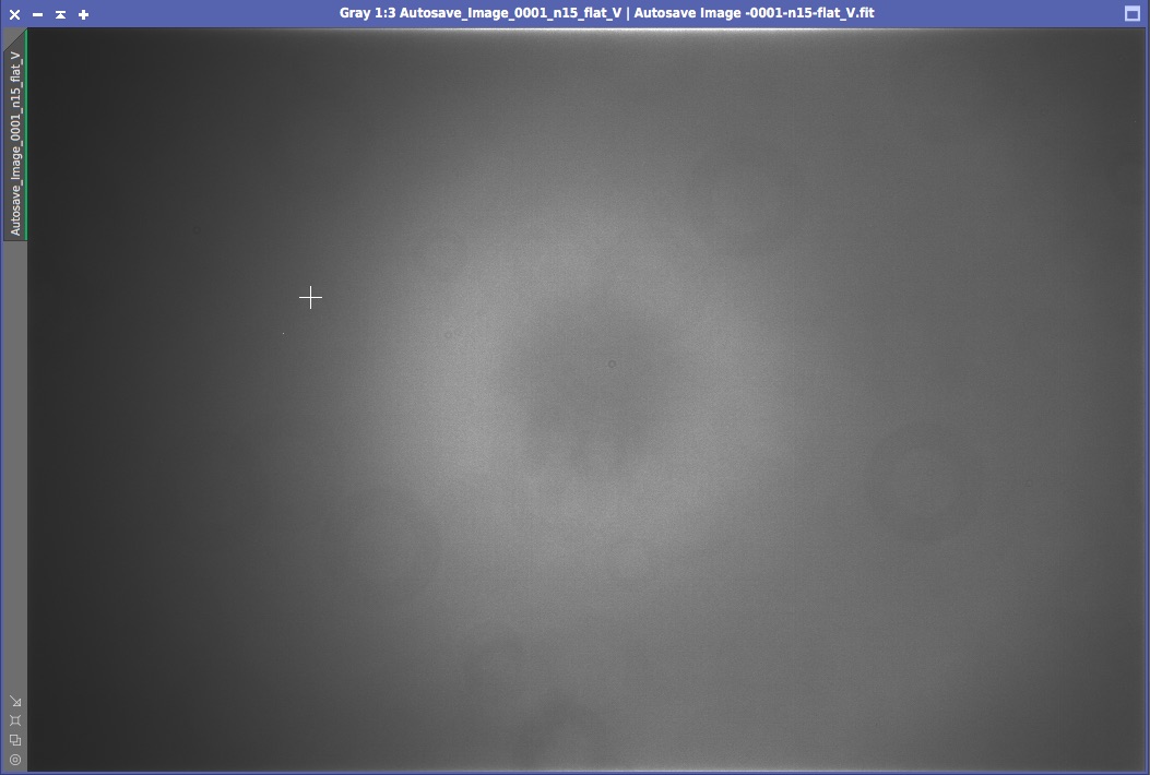
This is an image taken through the optical system at an evenly illuminated neutral white light panel or source. This information is then divided out of the final light frame to remove the effects of uneven chip sensitivity often caused by such things as the chip itself, optical path vignetting, and the like. If you do photometry, flats are essential. Take 30 or more flats which will then be averaged together to improve results. Some software, like MaxImDL, will allow you to use the same library of darks and biases to process the flats. Yes, flats also need to have darks subtracted AND biases subtracted! Also, if you use filters, you must take a series of flats through each filter you intend to use that evening. Also… you need to take your flats at the same temperature as the imaging session. Want to know more about taking flats: Here is my article on that very topic.
What is Binning?
Some cameras allow the user to be able to combine the information from a group of pixels (2×2 or 4×4) instead of just single pixels. This makes the effective pixel size larger. The net effects include: a decrease in image download times (good for quick focus); smaller image size; greater light sensitivity; a loss in resolution. It is possible to bin in order to match pixel size with an optical system’s focal length.
What is Gain?
Gain is a measure of a CCD’s efficiency. Each pixel element collects electrons. This number of electrons is then counted and converted into a digital value via an analog-to-digital conversion process. The minimum unit of counting is called an ADU (Analog to Digital Unit). Gain is measured in the number of electrons per ADU. In general, the lower the gain, the better the system. The point to remember is that the CCD’s efficiency also depends upon the total well depth of the system. This is the total amount of electrons that a pixel can hold before becoming full. If the well depth is greater than the A-to-D conversion gain, then a loss of a chip’s usable sensitivity will occur. For example, if a chip’s pixels can hold 90,000 electrons (well depth), and the chip gets 1.0 electrons/ADU in gain, if it is a 16-bit A-to-D conversion, the imager can count only 2^16/1.0 electrons per pixel. This is a loss of 90,000-65,536 electrons per pixel. Most modern CCD imagers account for this and also balance between higher noise and a suitable gain.
What is Correlated Double Sampling?
One may read that a particular imager uses correlated double sampling to reduce readout errors (noise) in the system. This method involves injecting a sum of electrons (charge) into the readout register on the CCD chip so that it reaches a known level. The image electrons are then transferred into this register and read out by the system. The known level (reference charge) is then subtracted from the count to give the actual pixel value.
What is Dynamic Range?
This is the ratio between useable ADU to the read noise of the system. An example: If a CCD has a well depth of 100,000 electrons and a readout noise of 13 electrons, the dynamic range would be 10 log(100000/13) which is 39dB or 13 bits. It is easy to see that even a 16-bit imager can not readily use all 16 bits worth of A-to-D conversion if there is a lot of noise.
What camera is best?
The single most important aspect of imaging is getting a good match between pixel size and the focal length of your telescope. This can easily lead to a deep arithmetic treatise, but let us just say these words… Your average seeing conditions will allow you to get between 1.3-4.0 arc-second wide star images. Average nights in my area rarely allow for those smaller values. This information allows one to guess that a good imager should use a couple of pixels to cover one star’s image. This would be a value of 2″ per pixel. This would allow you to use the chip to its maximum ability while still getting good-looking stars in your images. Using too many pixels to cover a star’s image will surely get you a finer “grain”, but would be a waste of your imager’s light gathering ability. If you are imaging the Moon or the planets, then using as many pixels as possible across the planet’s image would be in your best interest. In this instance a sky coverage of 0.5″ (or less) per pixel would be best.
Cameras for science? Cameras for pictures?
Choosing a CCD imager requires that you now what you want to get into imaging for! Do you want to take images like those seen in magazines? Do you want to get into supernova hunts or asteroid searches? Maybe stellar photometry interests you? Each of these specializations could benefit from using a different type of imager.
Pretty Pictures:
You have seen those magnificent images in Sky & Telescope, Astronomy and online. What is the best equipment for being able to take images like that?
Immediately recommended is the anti-blooming (ABG), thermally controlled CCD imager. Imagers with ABG allow one to take images of objects that have wide ranges of brightnesses without getting those ugly-looking streaks of light caused by too big a buildup of electrons on a photosite on the chip. These electrons then spill over to the next pixel and so on causing streaks like those seen below:

Another option to avoid blooming is to take a series of shorter integrations of the desired object then later add them together into a single image. This allows the faint details to be brought out and keeps the bright stars from blooming and ruining the image. An example of this technique is the below image of M-77. It is an addition of 10 one minute integrations with ST7, C-8 at f/6.3. A Dark frame was subtracted from each image before addition and Digital Development (in MaxImDL) was used to bring out details.

Thermal control of an imager’s chip allows one to significantly reduce the amount of dark signal (thermal signal) produced within the CCD chip itself. In the chip the actual substrate materials actually vibrate due to heat, and create electrons in the photosites. This is often called “noise” but really it is a signal form that is readily removed by subtracting a “dark frame” from your images during processing. A dark frame is just an image taken for the same time duration as your “light frame” (the image of the desired object) and taken at the same temperature. Processing softwares provided with the imager then allows you to subtract this unwanted signal from your image. Below is a graph to demonstrate the worth of a CCD cooling system. The author made this with an ST-7 by taking a series of five-second dark frame integrations, each at a different temperature on the chip. The average pixel brightness value was then calculated in MaxImDL’s Information Screen. It is obvious that the dark current values decrease rapidly as the temperature decreases. The value in being able to control the temperature on the chip is that one can save a series of dark frames at known temperatures for later subtraction in the comfort of the home the next day. Some popular cameras do not have temperature regulation, but do have thermoelectric cooling. This is better than no cooling, but the user must take dark frames while outside at the telescope to insure that the temperatures of the image and the dark frame are equal. This can become tedious when one is tired. This can be difficult if the local ambient air temperatures are changing rapidly too.
For those imaging nebulosity, the analog to digital conversion method should also be mentioned here. You will see references to 8-bit, 12-bit and 16-bit imagers on the market. Go for the larger value. This determines the amount of separate levels of grey that your imager’s A-D converter can separate the output into. Thus an 8-bit converter will give you 2^8 grey levels possible, where a 16-bit imager will give you 2^16 grey levels. The 16-bit CCD imager will thus show a finer gradient between grey levels, which is more pleasing to the eye.
Photometry:
Those interested in doing photometric work (the precise measurement of an object’s brightness) will want to avoid cameras that have anti-blooming gates installed. The reason for this is that as the charge builds up on a photosite the response becomes non-linear the closer it gets to blooming in a ABG CCD chip. That makes measuring the brightness very difficult by introducing non-linear equations. It is much easier to measure magnitudes with software if the CCD’s response to light is linear throughout the length of the integration. One still can not allow the object’s light to bloom across the pixels. Another benefit of non-ABG systems is that they are more than 10% more sensitive to light than ABG system making the time for an integration shorter.
Those wishing to do photometry will also want to invest in special filters and a filter wheel to change between them. These filters are standardized research grade filters that allow only certain regions of the light spectrum to pass through. More information about this can be gotten from the American Association of Variable Star Observers (Links to an external site.)Links to an external site. or the Center for Backyard Astrophysics (Links to an external site.)Links to an external site.. For those just starting out, a single V photometric filter (V = visual) will get you started on your way and will provide valuable scientific data.

Asteroid and Supernova Hunting:
The same basic rules apply here as they do for Photometric-capable CCD imagers, only one would be looking for a wide field of view. You can either get a large chip (very expensive), or get a chip with small pixels and use it on a short focal length lens. Supernovae hunters can use a 9-micron pixel CCD chip with a 50″ focal length system and be able to image thousands of galaxies: enough for a lifetime of study! Since measuring the object’s brightness is important, non-ABG CCD’s should be used. Square pixel systems are also very helpful when it comes to astrometry, the precise measurement of an object’s location in the sky. Software such as Guide and Astrometrica are also important for astrometry. Those interested should visit IAU: Central Bureau for Astronomical Telegrams (Links to an external site.)Links to an external site. and read on the process for reporting “discoveries”.
Color:
Making color images is no longer as difficult as it used to be. There are two options available to the astronomer now: color filter wheels and color CCD chips. The latter of the two options is available today through Starlight Xpress and their unique color CCD imager, the MX-5c. It can take a single image that is later combined with its color values to create a full color image like this:

For those wishing to use monochrome CCD’s to take color images there are a variety of filter wheels and sliders available that allow one to image through clear, red, green, and blue filters for later combination into a color image (tricolor). These filter systems are integrated into the CCD control softwares allowing for easy remote and automatic operation. The issue is time: For tricolor CCD imaging one must image the same object three or four times (depending on your technique) then later combine them. The following was taken using these techniques:


Helpful Devices (and additional cost):
Buying a telescope and a CCD imager is not the end of the road as far as equipment is concerned. It is really just the beginning. Here are some more items that are quite helpful.
Flip Mirrors & Slide Mirrors:
Many amateurs start out by trying to find an object in an eyepiece, then replacing the eyepiece with the imager. This is one of the most difficult methods of finding and centering an object on a CCD chip’s tiny surface. Many companies make flip mirrors or slider mirror assemblies which help to both find and focus on an object for imaging. Several on the market also act as off-axis guider ports for guiding.
Filter Wheels/Sliders:
Interested in color imaging or photometry? Filter wheels are available that work in concert with popular imagers and their software. They hold the necessary color filters for doing tri-color imaging or photometric work. Be aware that these devices, like flip mirrors and guiders, all require a longer backfocus from your telescope optics. Some telescopes will not be able to reach focus given the use of a focal reducer and a flip mirror. Contact the telescope manufacturer for details on their backfocus. Contact the equipment maker for details about their backfocus requirements.
Off Axis Guiders:
The off-axis guider is necessary if you are not using a self-guiding CCD system like an ST-7 or ST-8. Those cameras have second smaller CCD chips that act as guiding chips while the larger main chip takes the image. Other CCD makers are using various techniques to allow the imaging chip to guide the telescope while imaging at the same time. Be aware that guiding is very important in CCD imaging. One is trying to keep a star centered on a couple of pixels. That is a fine requirement. Typical off-axis guiders allow one to place a guiding eyepiece or an autoguider like an ST-4 into a port which picks off a small amount of the telescope’s light cone for tracking on a star. Autoguiders are by far a lot easier to use than guiding manually, but it is suggested that manual guiding be done at least a few times just to get familiar with the mount’s errors. When selecting off-axis guiders, also investigate flip/slide mirror devices as they can often be used as an off-axis guider.
Guide Scopes:
Guide scopes are another option when looking into guiding solutions. They allow one to be a bit more flexible in finding a suitable guidestar. They are also useful if the main optical assembly doesn’t have enough backfocus to accommodate a flip mirror assembly, or if a Fastar lens assembly is being used. Most guidescopes are refractors of a focal length equal to or longer than the main optics. This allow for guiding par with the resolution in the main scope. Using a shorter focal length would cause star images to be larger and less pinpoint. Another issue to remember is if one intends to do long exposure imaging with a Schmidt-Cas telescope, the main mirror might flop inside its cell as the scope guides (especially through the meridian). Off-axis guiders are the only real solution to this problem unless you install lock down bolts on your main mirror, a task not intended for the faint of heart!
Mounts:
This is another key to successful imaging. Many of the commercial mounts these days are not really up to the task of guiding, but they can be used with a few precautions. Make sure it is polar aligned well: do not just aim the polar axis at Polaris and hope to guide out the errors. This will just produce field rotation issues.
Make sure the mount is as sturdy as possible. Check for loose bolts and wires that could cause vibration. Use the counterweights to accurately offset the optical tube weight. Make sure all electrical connections are solid and supported with tape. There have been many frustrating nights trying to figure out why a certain axis would not track in one direction: a broken connector was the problem.
If you are looking to buy a new mount, this is one area where more money spent equals more quality product. Get a solid and reputable piece of equipment that is built to hold more than twice your current optical setup’s weight. You will not be disappointed. Get something with built in dual axis drive controls with an autoguider input. These are rapidly becoming standardized for most autoguiders and CCD imagers with guider outputs. If you ever intend to make the telescope permanently sited, check to see if the mount’s equatorial head can be placed on a permanent pier without too much machining.
A common question is: Can I use an alt-azimuth mount to do imaging? The answer depends on the type of imaging you wish to do. If you are going to do planetary or Lunar imaging, then, sure, you can do it. The integration times will be under one second most of the time. Long duration integrations will not be possible unless one obtains a field derotator, an electric device that attaches to the focus of the scope to rotate the imager opposite the direction of the field’s rotation through the integration time. Most people find that the cost and added possiblity of all these electric motors failing in the middle of the night is not worth it. It is much simpler just to have an equatorially mounted scope.
Software:
There are bunches of options in this category. All commercial CCD imagers come with their own software which allow for the basics of processing. Eventually better software will be desired. Choices range from freeware and shareware on the net to more expensive solutions like MaxIm DL (Diffraction Limited) or PixInsight (Pleiades Astrophoto). If you are looking for options, investigate the processes like Lucy-Richardson Algorithms and Fast Fourier Transforms. There are many things that a good image processing package can do for one’s images. Some packages also handle the taking of the exposure automatically in series with filter wheels, dark frames, and are even scriptable!
Methods:
Finding the Object:
One of the most frustrating processes is to find the object you are looking to image, and then getting that object centered in the field of a small CCD chip. Many people start out by tring to center the object in the view of an eyepiece, then replace the eyepiece with a CCD imager. This is a poor method as the weight of the imager often causes the view to shift. It is highly recommended that a flip mirror or slider mirror device is used. These have a moving mirror that either allows the starlight to get to the imager chip or be sent through an eyepiece for focus and centering. They are made so that the CCD chip and the eyepiece come into focus together. That makes the tough job of focusing a bit easier to do. Some models also have a third port that is used for guiding. These have a small pick-off mirror or prism like an off-axis guider that grabs the light from the edge of the scope’s field and sends it to either a guiding eyepiece or an autoguider.
Either way, one still has to find the object to image. The use of software is a great way to accomplish this end, since a computer is available anyway for the control of the CCD imager! Applications like theSky (Software Bisque). even allow one to place a box representing the CCD field of view on the star chart. Programs also have integration with many popular digital setting circles. These handy, though expensive, devices act as a digital representation of mechanical setting circles on one’s mount. The nice thing is that they also contain whole searchable catalogs of objects (NGC, Messier, etc). One can also star-hop using an atlas, which is an art form in its own right and is a lot of fun.
Focusing:
Just when finding an object is getting frustrating, focusing on it can also be as patience testing. Spend a lot of time focusing. It can really boost the quality of an image. There are a lot of ways to focus:
- Full-width-half-maximum
- Visual
- Parfocal eyepiece
- Diffraction method
- Maximum brightness
Of these, the simple visual method is the least precise. With modern SCT’s, a very popular scope design, 1/500 of a turn on the focus knob will throw the image out of focus enough to degrade a high resolution image.
Full-width-half-maximum (FWHM) is a method found in some imaging software that is very precise. It is the measure of the width of star image across the pixels where the pixel levels are half the maximum brightness of the pixels for that star.
Other softwares allow the user to view the brightness of the star images. By achieving the highest brightness value, one can state that they have achieved best focus.
A parfocal eyepiece is simply an eyepiece that is in focus at the same time as the CCD chip itself. This is usually in some sort of flip mirror device. The use of a parfocal eyepiece is very helpful in obtaining near focus conditions. It is by no means the way to achieve best focus. It is great for finding a rough focus on an object, but that is all. Do not be misled by some advertising claims that state that one can focus and be imaging by use of a parfocal eyepiece. The human eye readily accommodates to slightly out of focus images in an eyepiece. What appears to be in focus to the eye may not be in focus on a CCD chip. If you have to use this method, then use a very high power eyepiece (4mm focal length). The eye has a more difficult time accommodating to these than, say, a 25mm eyepiece.
The diffraction method of CCD focus is another fine way of reaching accurate focus. It is somewhat more time-consuming, and requires a piece of home-made equipment for some scope types, but is not difficult. In short, some sort of rods or diffraction spike-causing object is placed in front of the scope’s objective. This causes diffraction spikes to be produced around brighter stars in a CCD image. Another similar method is the use of the Hartmann Mask. This is a dark mask or disk with a few holes cut in it. This is then placed over the front of the scope causing multiple images of a star when the star is out of focus. When in focus, the star’s images become one.
Guiding:
Guiding is done in a couple of ways: autoguider, self guider, or manually. It is not recommended that manual guiding be done, though it is possible with the relatively short integration times of modern CCD imagers. The accuracy of manual guiding is the problem. The SBIG ST-4 and STi are full-featured autoguiders and imager, allowing one to see the star for focusing and centering. Both hook up to the guide port in modern mount electronics. This tells the scope’s mount which way to correct as stars drift due to improper polar alignment or periodic error. It is just as important to focus the autoguider as well as the main imaging camera.
Some CCD imagers have built in secondary guider chips, like the SBIG ST-7 and ST-8. These chips are at the same focal plane as the imaging chip, so focusing one automatically focuses the other. That is very time-saving.
Either way, the use of an autoguider is pretty much the same. Find and center a guide star on the guider chip. Make sure everything is focused, then train the guider as to how it has to react to fix various directional guide errors. This is done via a process called calibration. It involves the guider moving the mount in each of the four directions (+/- RA and +/- Dec) and taking an image at each position. It then looks for the same star in each image and calculates its correction values for the mount, the declination, and the guider’s orientation on the field of view. It’s pretty neat mathematics and a real time-saver.
The latest in self-guiding technology is from the Starlight Xpress company in the United Kingdom. They have developed a process using their chips which captures signal information on even rows of pixels while reading the odd rows for guiding. Halfway through the exposure, the rows are switched so that the even rows are used for guiding while the odd rows are then used to capture image signal. The result is longer required integration times, but with self-guiding! This is called the STAR 2000 system.
Taking the Image:
Once the telescope is centered on the object and guiding, it is time to actually take the image! This is the easy part! Tell the software to start imaging for the amount of time that is desired. If you are using a non-ABG imager, then you may want to limit the integration time to just under where blooming begins with the field’s brightest stars. Also be aware of the imager’s temperature. If it has no control over the cooling, let it stabilize for at least 10 to 15 minutes before imaging to get the best results. Be sure to take a dark frame as soon as the image is complete. For those with controlled cooling, just be sure that the imager has reached its set-point (the temperature you have set the cooler to obtain) and image away!